Categories

Archives

What are the different types of flexible multilayer PCB for various industries?
By Mer-Mar Electronics | Date posted: | Last updated: November 25, 2022
Flexible Multilayer PCB

Flexibility is the cornerstone of great design and that is something that is made possible by flexible multilayer PCB.

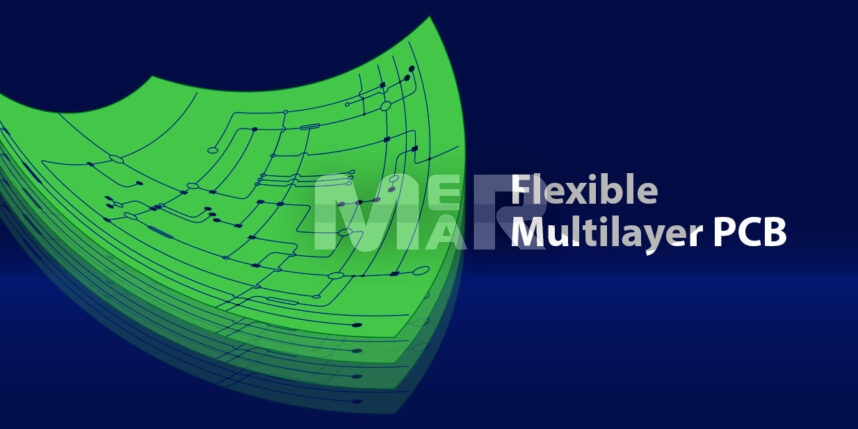
A flexible printed circuit is a circuit board with a flexible construction. It is also known as a flex circuit. It is used in small electronics. A flex circuit largely consists of two or more copper conductive layers with an insulation material between its layers. There is also an application of coverlay in the flexible areas that can protect the external circuitry of a flexible PCB

Different configurations of flex printed & rigid-flex circuit boards

Flex and rigid flex PCB are available in a wide range of configurations and can be found in different applications. These include:

  • Single-layer flex printed circuits – Such circuits adhere to IPC 6013, Type 1 standards & have a single copper conductive layer between two insulating layers. These work well in bend-to-fit applications.

  • Double-sided flex printed circuit – Adhering to IPC 6013, Type 2 standards, these consist of two copper conductive layers with insulating polyimides. Plated through-holes ensure circuit connectivity between the layers. Such circuits work well for dynamic flex as well as bend-to-fit applications.

  • Multilayer flex printed circuit – Adhering to IPC 6013- Type 3 standards, they have three or more conductive layers with insulating layers in between. They also make use of plated through-holes for ensuring connectivity between layers. They also use high-speed controlled impedance and work well for bend-to-fit applications.

  • Rigid-flex printed circuit – They adhere to IPC 6013-Type 4 standards. These have two or more copper conductive layers with insulation in between. They also have plated through-holes that cut through the rigid as well as flexible layers. In addition, there is an application of coverlay on the flex layers.

Of these, let us look at multilayer flex circuit boards in greater detail:

YOU MAY ALSO LIKE: 2 Layer VS 4 Layer PCB

Multilayer Flexible Printed Circuit Boards

One can look at multilayer circuits as a combination of several single layer or double layer circuits. Multilayer circuits can in turn come with:

  • Continuous lamination
  • Without continuous lamination

The choice of the above depends upon whether you are looking at maximum flexibility in your multilayer PCB designs. For designs that need total flexibility, it is an easy decision that continuous lamination is not suitable. Multilayer flex circuits work particularly well in the following scenarios:

  • Specified impedance requirements
  • When you need to eliminate crosstalk
  • Where there is extreme component density, and more.

In fact, if one were to look at the benefits of multilayer flex printed circuits, these would include:

  • High circuit density
  • No need for mechanical connectors
  • Flexibility in design
  • Reduction in weight as also size
  • Ability to function in high operating temperature range
  • Reduction in wiring mistakes
  • Improved signal quality
  • Improved impedance control

In addition, with multilayer flex PCBs you also tend to benefit from:

  • Reduction in assembly errors. This is because they do not use hand-built wire harnesses and make use of automation in production.
  • Reduction in assembly time. Because the multilayer PCB assembly doesn’t require too much manual labor, both the assembly time & the cost are kept under check.
  • High applicability. Flexible circuits also offer a lot of design freedom and therefore lend themselves to many applications. They also offer flexibility during installation without losing functionality. Importantly, they lend themselves to high-density component placement which is a great plus in today’s times of miniaturization.
  • Improved airflow. With their designs offering improved airflow, increased product lifecycle is a given. Their compact design also lends itself to better dissipation of heat.
  • Increased reliability. With fewer interconnections what flexible multilayer printed circuit boards also offer is increased reliability. That they are durable and can withstand elevated temperature conditions is an added advantage.

Because of all these factors & particularly the fact that they lend themselves to small size applications, multilayer flex circuits are so much in vogue. That they can withstand harsh environmental conditions is another advantage as that means that they can be deployed in tough environmental conditions.

It is however important to select the right contract PCB manufacturer that has the requisite experience & expertise with multilayered boards. They are equipped with robust PCB design software as well as industry best practices that ensure you do not have to deal with costly errors later that can lead to product recall and even cost the company’s reputation. If you are dealing with mission-critical operations, the use of multilayer flex circuits particularly cannot be overestimated.

Mer-Mar Electronics is an ISO 9001:2015 certified company and ITAR (International Traffic in Arms Regulations) compliant manufacturer that delivers multilayer PCB fabrication services with specialized support, reliable testing, and multi-functional features. In case you have any questions or require more information about PCB assembly and fabrication services, get in touch with us via sales@mermarinc.com or call us on (760) 244-6149.

Flexible Multilayer PCBs
Multilayer Flex PCB
Multilayer Flexible PCB
Multilayer PCB Assembly
Multilayer PCB Board
Multilayer PCB Design
Multilayer PCB Fabrication
Multilayer PCB Manufacturer
Multilayer PCB Manufacturing
Multilayer PCBs
Multilayer Printed Circuit Boards
Multilayer Rigid Flex PCB

Best strategies for managing printed circuit board material in high frequency applications!

By Mer-Mar Electronics | Date posted: | Last updated: June 20, 2022
Printed Circuit Board Material

Effective material management is imperative in all aspects of our lives. However, for PCBs, especially those which work in high-frequency applications, the choice of the right material is beyond crucial. The performance of the board is often seen as a function of component placement and trace routing. However, it is the circuit board material that offers a strong foundation.

Let us look at some of the benefits that high-speed board materials offer:

Benefits of High-Speed Board Materials

The major benefits of high-speed board material include:

  • Impedance Control – High-speed board material has a dielectric constant of +/- 2% or better. For circuits that require controlled impedance routing this is extremely important.
  • Signal Performance – A lower dissipation factor that helps to reduce signal loss is extremely important especially as the frequency of transmission line increases.
  • Dimensional Stability – In a high-frequency design it is imperative that tight physical tolerances be maintained. Laminate materials that offer mechanical stability are therefore key.
  • Moisture absorption – A small amount of moisture can also come in the way & impact electrical performance.
  • Thermal Management- For boards that have to be used in harsh environments, materials with excellent thermal properties need to be chosen.

The above are the exact reasons why FR-4 has a number of operating limitations that affects its efficacy. Some of these include:

  • FR4 is rated at a dielectric constant of ± 10% or more, that does not give it the tolerance that is required for high-frequency designs.
  • It has a high dissipation rate when it comes to signal loss.
  • Its moisture absorption rating is nearly 50%, that can affect electrical performance of the board.
  • It also has limitations in terms of thermal management & therefore is not suitable for high-temperature operating conditions.

PCB Material Management for High-Frequency Designs

The demand for high-frequency PCB manufacturing is on the rise in several sectors including but not limited to:

  • Automotive radar systems
  • Satellite antennas
  • Cellular telecommunication systems
  • Broadcast satellites
  • RFID tags
  • Missile Guidance systems, and more.

For these and many other sectors, there are a number of circuit board materials that work particularly well. Some of these include:

  • Epoxy resins – This category, of course, includes FR4 which suffers from some weaknesses when it comes to higher frequencies.
  • Enhanced epoxy – These materials tend to improve the performance as opposed to standard FR 4 & related material.
  • Polyimide – Such material can withstand harsh conditions with their excellent thermal & mechanical properties. Additionally, they are chemical as well as moisture resistant.
  • PTFE (Polytetrafluoroethylene) – Also referred to as Teflon, such materials offer high impedance control as well as signal performance making them highly suitable particularly for wireless communication systems.
  • Thermoset hydrocarbon laminates – These are particularly known for their mechanical stability although at higher frequencies they may show dielectric loss.

There are a wide variety of materials available for high frequency applications. Some of the aspects to be mindful of, however, include:

  • Such material comes at a higher cost. You therefore need to look at a cost-performance trade-off in making your choice.
  • Sometimes you will need to evaluate exactly how much performance improvement your circuit needs. After a close evaluation, you may at times want to settle for FR-4 or one of its enhanced versions.
  • Many of them require non-standard fabrication processes adding to fabrication & assembly cost.
  • They may require changes in solder types as well as cleaning processes that impact both manufacturability & price.

To Sum Up

Given the criticality of the operation & the many factors to be considered in choosing the right material, the one thing that is non-negotiable is to choose an experienced electronic contract manufacturing partner who can guide you through the choice of material. The contract manufacturer will be able to undertake the right cost-benefit evaluation to choose a material that meets your criteria without escalating the cost to unacceptable levels. Additionally the contract manufacturer can also help you with the right board layer stack up strategy. You can also use some sophisticated design tools that are meant for high frequency designs.

Our experienced PCB material management team and advanced material management system can efficiently manage your projects and requirements. We have the resources available to locate parts and materials you need to eliminate the delay and reach quickly to the result. In case you have any questions or require more information about PCB Manufacturing, contact us via sales@mermarinc.com or call us on (760) 244-6149.

PCB Manufacturer
PCB Manufacturer USA
PCB Manufacturing
PCB Manufacturing Services
PCB Manufacturing USA
PCB Material
PCB Material Management
PCBs
Printed Circuit Board
Printed Circuit Board Material
Printed Circuit Boards

What Is the Purpose of Copper Thieving in PCB Development?

By Mer-Mar Electronics | Date posted: | Last updated: October 21, 2022
Copper Thieving in PCB

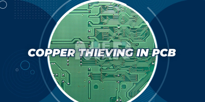
Copper thieving in PCB refers to adding non-conductive patterns of copper to the printed circuit board. This is done to even out the electrical current used for plating the board. In the absence of this, there can be areas of the board that are isolated and where current can become more concentrated. This results in the often-seen “mushroom” profile caused on account of under-etching. In turn, in an impact both the electrical performance of the trace as well as its structural strength.

To avert these issues, adding copper thieving in the areas of the circuit board where the metal is sparse is effective. It ensures that the same amount of copper is distributed throughout the board so that the plating current is applied equally and the traces will all etch the same amount.

Thieving is seen by way of an array of dots or diamonds added to what would have otherwise been an open area on the board. It is important to remember that if there are any areas on which you specifically do not want any thieving to be added, the same needs to be mentioned on the fabrication drawings. Typically thieving is avoided in the following areas:

  • Where it interferes with the controlled impedance elements on the board.
  • Where you require a smooth area to pace a label.
  • In case it violates creepage or clearance rules.

YOU MAY ALSO LIKE: OVERCOME PCB FABRICATION ERROR

Advantages of Copper Thieving in PCB

1. Etching and Plating Control

The big advantage of copper thieving is that it makes the copper distribution uniform which helps make etching & plating seamless and ensure that different copper densities do not plate and etch at different rates. In the absence of copper thieving copper features such as traces, pads, plated vias and more that are in a more sparsely populated area tend to over plate as opposed to those in more densely packed areas.

2. Consistency in Thickness

Thieving evens out the thickness of the finished board. If a design involves most of the copper layers being stacked on one side, there could be a noticeable change in thickness on one side as opposed to the other. Copper Thieving tends to bring about consistency in thickness in finished boards.

YOU MAY ALSO LIKE: STEP BY STEP PCB FABRICATION PROCESS

3. Minimize Bow and Twist

With uneven copper distribution, a big disadvantage is PCB warping and twisting. This is seen more so during high PCB assembly or when copper begins to heat and expand. Copper thieving goes a long way in minimizing warpage.

4. Control Dielectric Thickness Between Layers

Thieving is also an important way to control the dielectric thickness between copper layers. During the lamination cycle the layers are stacked together using pre-preg. Once it is heated the pre-preg liquefies and fills the gaps between the copper features. By doing this, it ensures no air is trapped inside the board. With uneven copper distribution, you will often be left with inconsistent dielectric thickness.

5. A Caveat About Thieving

While the advantages of Copper Thieving are many, it is important to keep in mind the fact that if there are traces on the layers just below where thieving has been added, it can impact the impedance of these traces. It is imperative therefore to add a note to your fabrication drawing to state that thieving should not be done in these areas.

To Sum Up

Thieving is an effective method to ensure that there is uniform plating of copper. To ensure this the plating current needs to be uniformly distributed over the PCB outer layer surfaces. It is imperative that you work closely with your PCB Contract manufacturer so that the copper thieving works for both plating and signal performance needs of the board. An experienced contract manufacturer will understand these requirements and can advise you on the creation of the thieving patterns. It is critical that any metal changes to the board are undertaken by the design engineers, who can look at the issue holistically, and can take all of the potential effects into account. It is important to remember that there is a lot to consider when adding copper thieving to a printed circuit board hence the experience and access to best practices of the contract manufacturer are priceless.

Mer-Mar Electronics is one of the leading PCB design and manufacturing companies, providing all in one PCB assembly and PCB fabrication solutions. Our consistent quality and quick turnaround endear itself to our customers, who look on us as a one-stop-shop for all their PCB manufacturing requirements. In case if you have any questions or require more information about our services, contact us via sales@mermarinc.com or call us on (760) 244-6149.

Copper PCB Fabrication
Copper PCB Manufacturing
Copper Thieving
Copper Thieving in PCB
Copper Thieving PCB
PCB Copper Thieving
PCB Development
PCB Manufacturer
PCB Manufacturing
PCBs
Printed Circuit Boards
USA PCB Manufacturer

Top materials to consider while manufacturing lead-free PCB!

By Mer-Mar Electronics | Date posted: | Last updated: February 28, 2023
Lead-Free PCB

If you are to comply with the RoHS directive, you need to select lead-free PCB manufacturing material. The directive limits the use of the following:

  • Cadmium
  • Mercury
  • Polybrominated biphenyls
  • Hexavalent Chromium
  • Polybrominated biphenyl ethers

In choosing the right lead-free material you need to check for several things including:

  • The ability of the material to withstand elevated temperatures.

PCB materials that comply with the RoHS directives need to use a lead-free solder paste and undergo a soldering process at high temperature. This requires the PCB material to have the following properties:

  • High glass transition temperature
  • High PCB decomposition temperature
  • Low thermal expansion coefficient

    • Compatibility of solder and PCB pad coatings.
    • Low dielectric loss.
    • Low dielectric constant.
    • High insulation resistance.
    • Low water absorption.

YOU MAY ALSO LIKE: What is RoHS Compliance

SELECTING A LEAD-FREE PCB MATERIAL

Depending on the complexity of the product, a PCB needs to have a large number of layers, high component density, large surface area and more. The reliability of these boards has a lot to do with the choice of the right PCB material. The following thumb rules based on the product function and performance come in handy to ensure reliability of lead-free PCBs:

  • Lead-free FR-4 epoxy glass fiber substrate works well for general electronic products.
  • High TG FR-4 material works well for complex electronic products.
  • Lead-free FR-5 material is appropriate for high-reliability electronic products.
  • Lead-free CEM-1 and CEM-3 materials work well for low-cost electronic products.
  • Flexible PCBs use polyimide glass fiber substrate.
  • High-reliability circuit boards need metal substrates.
  • For high-frequency circuit boards Teflon glass fiber substrates work best.

LEAD-FREE LAMINATES

It is also important to select high-temperature laminates in order to meet the high-temperature cycling requirements especially as some lead-free PCB assembly processes require the laminate to withstand temperatures in excess of 260 °C for extended periods of time.

Some of the popular lead-free PCB laminates include:

LEAD-FREE SOLDERMASK AND SURFACE FINISH

Lead-free PCBs necessitate the use of solder masks containing chlorine. Halogen-free solder masks are also widely used in the case of lead-free PCBs.

The surface finish plays a crucial role in the PCB as it prevents the copper from oxidation and thereby ensures high performance. The surface finish is also essential in making a reliable connection between the PCB and the components. It is imperative, therefore, that the choice of the surface finish be made with the same level of dexterity as in choosing the right material for the bare board.

Some of the lead-free surface finishes that are increasingly used, include:

  • Electroless Nickel Immersion Gold or ENIG.
  • Electroless Nickel Electroless Palladium Immersion Gold or ENEPIG.
  • Electrolytic Nickel/Gold.
  • Immersion Silver.
  • White Tin or Immersion Tin.
  • Lead Free HASL.
  • Organic Solderability Preservatives or OSP.

A wide variety of factors such as the cost, the operating environment, shelf life, production volume and throughput are some of the other factors that impact the choice of the surface finish.

TO SUM UP

It is imperative that the board of designers provide specific information in the purchase order confirming the material type, the final finish and requirement for RoHS compliance. This will ensure that the right products are used that support recycling and reuse along with meeting legislative directives. In fact, it is time for the industry to step up to eliminate hazardous materials from PCBs. This not only means phasing out a lead but also being proactive in recognizing materials that may not be prohibited yet but do not have a stellar reputation. With sustained efforts, not just the use of lead but other hazardous elements can also be done away with. That will mean not just saving the environment but also not scrambling to meet deadlines to do with the banning of hazardous substances. Choosing the right PCB partner is therefore of utmost importance as their expertise and experience can go a long way in making the right choice of material.

At Mermar Electronics, we specialize in providing lead-free and RoHS compliant PCB manufacturing services. Our high-quality lead-free PCBs are manufactured using environmentally friendly components. Our consistent quality and quick turnaround endear itself to our customers, who look on us as a one-stop-shop for all their PCB requirements. In case you have any questions or require more information about lead-free PCBs, contact us via sales@mermarinc.com or call us on (760) 244-6149.

Lead Free PCB Assembly
Lead Free Printed Circuit Boards
Lead-Free PCB
PCB Assembly
PCB Manufacturer
PCB Manufacturing Services
Printed Circuit Boards
RoHS Circuit Board
RoHS Compliant PCB Assembly
RoHS Compliant PCBs
RoHS Printed Circuit Boards
Back to top