Categories

Archives

IPC J-STD-001 Standard – Soldering Requirements for Electrical and Electronics Assemblies
By Mer-Mar Electronics | Date posted: | Last updated: November 28, 2022
j-std-001

J-STD-001 has emerged as an important IPC standard for soldered electrical as well as electronic assemblies. The standard lays down the following:

  • Material Specifications
  • Process Requirements
  • Acceptability criteria

Adhering to J-STD-001 standards essentially ensures that the soldering is of high quality & that it works well under different environmental conditions.

The standard was first released in 1992. Then known as J-STD-001 A, it has undergone several amendments with the latest version being J-STD-001H. Under the certification the following elements are included:

  • Material & components
  • Soldering requirements
  • Terminal & wire connection
  • Through-hole mounting
  • Surface mounting
  • Cleaning
  • Coating & adhesives

Difference between J-STD-001 & IPC-A-610

The similarity between J-STD-001 & IPC-A-610 is that both delineate the soldering process & the characteristics of an acceptable board. However there are several differences between the two standards, namely:

  • IPC-A-610 is an acceptable standard for electronic assembly acceptance
  • IPC-A-610 also lays down the board inspection procedures
  • J-STD-001 on the other hand deals with the material & processes for soldering in particular.

Let us look at some of the requirements as laid down by J-STD-001

Soldering Requirement as Per J-std-001

  • It lays due emphasis on cleanliness as contamination of material as well as surfaces can lead to errors & malfunctioning
  • It also lays emphasis on the heating & cooling rates. The use of chip capacitors ensures that there is due protection
  • It is imperative that strands of wires aren’t damaged.
  • Prior to the application of conformal coating a through soldering inspection needs to be undertaken
  • Any soldering errors need to be reworked
  • The use of Automated Optical Inspection & that of Automated X-Ray inspection is imperative

Industry Standard for Space Applications

In addition to this J-STD-001ES standard has been issued that applies to space addendum application. Some of the areas covered under that include:

1. Flux

Flux is categorized into RO & RE resin, which in turn has activity levels from L0 to L1. It is important to test the compatibility of the flux as well as undertake solder paste testing.

2. Material

In terms of material, it is important to validate as well as document any changes in flux, solder paste, cleaning media etc. Also, it is important to use solder alloys that are known for performance & reliability

YOU MAY ALSO LIKE: Right Material For PCB

3. Corrosion Plan

It is imperative to have a red plague corrosion control plan for silver-coated copper conductors

4. Chemical Strippers

The choice of chemical strippers needs to be done in a manner that it does not cause any damage. Also, it is important to protect components from thermal shocks. For this, the use of a heat sink, thermal shunt or more is recommended.

5. Mounting components

In terms of mounting of components, a suitable method needs to be followed so that the necessary temperature can be attained. Additionally there needs to be adequate clearance between parts. It is also important to offer stress relief to leads as well as to wires that attach terminals.

6. Exposed material

While exposed material is acceptable, the exceptions to this rule are components made of iron, component leads, Kovar & Alloy 42. Also, the exposed material should not hamper the process of forming the solder connection. Similarly, the OSP should not hamper the solder joint

7. Wire & Lead Ends

In terms of wire & lead ends, they should not extend over the terminal by more than one lead diameter. Also the electrical clearance requirements must be met.

8. Through-hole component soldering

In terms of through-hole component soldering, it is important that the PTH is completely filled with the solder.

YOU MAY ALSO LIKE: Through Hole Importance In PCB

9. Lead Length

There needs to be a minimum lead length. While for flat and coined leads it is two lead width, for round leads it is two lead diameters

10. Chip Components

In terms of chip components, there are separate requirements for rectangular or square chip length components as well as for cylindrical ones.

11. Surface Mount Area Array packages

The visual inspection requirements for array packages include an X-Ray or AOI inspection. The visual inspection must also cover the solder termination. In case of corner markers on the board, the area array components need to align in X & Y directions. There shouldn’t be errors in terms of absence of leads.

12. Ultrasonic Cleaning

Ultrasonic Cleaning is recommended when there are only terminals or connectors present on bare boards or where it is documented that the use of ultrasonics will not impact the performance of the assembly.

It is imperative that the J STD 001 training be attended by anyone who is in charge of soldering electrical or electronic assemblies such as assembly operators, quality inspectors, manufacturing engineers & more.

IPC Standard
PCB Fabrication
Soldering
Soldering Standard

PCB Gold Fingers: Types, Uses, Repairing & Its IPC Standard

By Mer-Mar Electronics | Date posted: | Last updated: November 1, 2022
pcb gold fingers

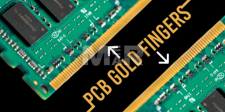
In a highly connected world, a big pre-requisite is for the numerous devices that we use, to communicate with each other. This important task is performed by PCB Gold Fingers. They serve as the connection between a secondary PCB to the motherboard of a computer. With the superior connectivity offered by gold, its use is spread across devices that communicate via digital signals.

PCB Gold Fingers

In essence, Gold Fingers are gold plated columns. Looking like fingers this is a long row of PCB pads along the connecting edge of PCBs.

Made out of flesh gold the big advantage that they offer is their superior connectivity. They are also known for their high corrosion resistance and electrical conductivity. The thickness of these Gold Fingers typically ranges between 3 to 50 microns.

YOU MAY ALSO LIKE: Choose right PCB fabrication services

Types of PCB Gold Fingers

Broadly PCB Gold Fingers can be classified into three types:

1. Normal PCB Gold Fingers

These are most commonly used and have an even array. Their PCB pads have the same length, width, and space.

2. Uneven PCB Gold Fingers

Their PCB Pads have the same width but differ in terms of length & spaces.

3. Segmented PCB Gold Fingers

The PCB pads have different lengths. Also, the gold fingers are segmented. These are widely used in many hybrid electronics especially the ones that are water-resistant.

PCB Gold Fingers Beveling

A bevel is created at the edge of the PCB sheet material that ensures PCB insertion in slots.

Angle for PCB gold finger bevel:

Typically, the angle for a PCB gold finger bevel is kept at 45 degrees. However, a 20- and 30-degree bevel is also sometimes preferred. The beveling angle also depends upon the size of the circuit board.

The beveling process involves cutting the edge of the PCB sheet material with the use of automatic beveling equipment. The beveling process is undertaken after the disposition of solder masks. Beveling ensures that the insertions are quicker and effortless.

YOU MAY ALSO LIKE: Silkscreen VS Solder Mask

Essentially the overall plating process comprises of the following steps:

1. Nickel Plating

The connector edges of the fingers are plated with between 3 and 6 microns of nickel.

2. Gold Plating

About 1 to 2 microns of hard gold is plated over the nickel. In turn, the gold is enhanced with cobalt for improved surface resistance

3. Beveling

Typically done at angles of 30 to 45 degrees they help in easier insertion on corresponding slots.

In the plating process some best practices that need to be kept in mind, include:

  • Inner layers need to be copper-free along the PCB edge. This will prevent copper exposure during the beveling stage.
  • Plated holes, SMD & pads should not be placed within 1 mm of the gold fingers.
  • There should be a distance of 0.5 mm between the gold fingers & the outline.

IPC Standard for PCB Gold Finger

Popular standards that are followed in the production of PCB gold fingers, are released by The Association for Connecting Electronics. The earliest standards relating to gold fingers were released in 2002. These were further improved in 2012 & released as the IPC-4556 standards. Of all the standards, the IPC A-600 & IPC-6010 standards of 2015 remain the most popular. Some of the guidelines to manufacture gold fingers include:

1. Chemical Composition

A gold plating consisting of 5 to 10% Cobalt helps in achieving rigidity along the edges of the PCB Gold Fingers.

YOU MAY ALSO LIKE: IPC-6011 Classes

2. Thickness

The thickness of the plating needs to be between 2 to 50 micro inches. The standard thicknesses are:

  • 0.031 inches
  • 0.062 inches
  • 0093 inches
  • 0.125 inches

3. Visual Test

A magnifying lens is used to conduct a visual test. It involves checking for smooth contact edges, clean surface as free as no excess plating.

4. Tape Test

It checks the adhesiveness of the gold plating. Essentially, a strip of tape is fastened over the contact edges and is subsequently removed. The tape is then inspected for any traces of plating. In case gold is visible on the tape, the plating is considered insufficient.

Benefits of PCB Gold Fingers

The major advantages that Gold Fingers offer include the following:

  • It offers excellent conductivity. The gold in the Gold Fingers helps maintain the necessary connections while also ensuring there is no damage through power use.
  • It ensures resistance to wear and tear as the PCB is plugged in and out.
  • The hard-gold plating process also lends good oxidation resistance to the PCB pads.

PCB GOLD FINGER REPAIR

Since they are at the periphery of the circuit board, Gold Fingers are prone to damage. Additionally, they are also prone to solder splash during wave soldering. This necessitates restoring the edge contacts to an optimal level of performance. The contaminated contacts are stripped & then replaced by the electroplating process. This ensures functional conductivity as well as durability.

Use of Gold Fingers in PCB

Gold fingers connect PCBs through a strong interlocking system. With gold being highly conductive the power goes through the connectors quickly. Additionally, the use of hard gold also protects the fingers from damage.

Gold Fingers can be used in a wide variety of ways, important among them are:

Interconnected Points

These are the parts of a PCB that connect it to other boards within the computer.

Special Adapters

These connect additional components to the PC structure. Such components include sound card, graphic cards, extra RAM space and more.

External Connections

These are peripherals such as monitors, speakers, and printers. With Gold Fingers high fidelity data transfer is made possible when using these peripherals.

PCB Gold Finger FAQs

1. How much gold is in PCB board?

The gold content in the PCB differs basis the type of PCB & varies between 140 and 700 g of gold for every ton of PCB.

2. What is ENIG finish PCB?

Electroless Nickel Immersion Gold or ENIG refers to a metal plating process. It helps avoid oxidation and improves the solderability of copper contacts as well as plated through-holes.

3. Are traces on PCB gold?

Three commonly used conductive metals include silver, pure copper and pure gold. The importance of the use of gold lies in the fact that it does not oxidize or tarnish. Hard Gold makes for a corrosion resistant and electrically conductive layer. Similarly, gold is also used in Gold Fingers. The gold plating on the edge of conductors protects the conductors from oxidizing & making them more resilient.

We provide cost-effective PCB fabrication and assembly all the while maintaining high-quality standards. Whether you need a small-volume or a high-volume production run our brilliant engineering team strives to reduce the assembly and fabrication costs for our client’s PCBs. We take a custom approach to determine what are the elements that are affecting the cost of production and how they can be tweaked or altered without compromising the functionality and quality of the PCBs.

You can reach out any time and ask our PCB assembly specialists about the quotes that match your budgetary targets. You may also contact our manager to review your quote and find out the cost-reducing options.

Get a quick PCB fabrication quote!

PCB
PCB Fabrication
PCB Gold Fingers

PCB fabrication process – A step by step complete guide!

By Mer-Mar Electronics | Date posted: | Last updated: December 26, 2022
PCB fabrication process

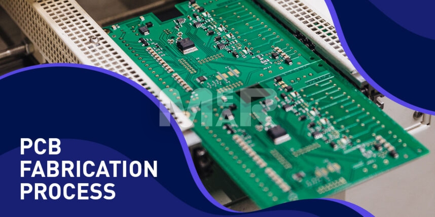
The use of PCBs (Printed Circuit Boards) has become quite ubiquitous as they bring electronic equipment-simple or complex, to life. Particularly in mission-critical functions where failure can be fatal, it is imperative that there are no errors in PCB fabrication. Here is a handy guide to the various steps of the process.

YOU MAY ALSO LIKE: Printed circuit board assembly process

PCB Manufacturing Process

1. Design

An important first step is the right design. At the PCB design stage itself, it is important to be in touch with the contract manufacturer. Among other things it is necessary to inform them of the design software being used so that there are no discrepancies. It is important that the design fulfills requirements for design for manufacturing (DFM) so that there are no issues faced at the fabrication stage.

2. From file to film

Post the DFM check, it is time for PCB printing. A special printer called a plotter is used for the process.

Each layer of the PCB and the solder mask gets its own clear & black film set. To ensure there is good alignment, registration holes are punched through the films.

3. Printing the Inner layers

In this step, the figure is printed on the film and onto a copper foil. The PCB comprises a laminate board where the core material is epoxy resin and glass fiber. Copper is pre-bonded on both sides. The whittling away of copper reveals the design of the films. Copper-sided laminate is cleaned. The clean panel next receives a photoresist, a layer of photo-sensitive film. Once the photoresist is exposed to ultraviolet light, it hardens. Once the board is prepared it is washed with an alkaline solution so that any photoresist that has not hardened is removed. The board is subsequently dried.

4. Removing the Unwanted Copper

At this stage, a powerful chemical is used to remove the excess copper. The desired copper, however, remains protected beneath the hardened layer of the photo resist. The hardened resist is now washed off with another solvent.

5. Layer Alignment and Optical Inspection

The inner layers are next aligned to the outer ones. The use of an optical punch ensures that registration holes are punched accurately. Automatic optical inspection of the panels is also carried out so that there are no errors.

6. Layer-up and Bond

In this step the layers are fused together. There are two steps involved

  1. Layer-up
  2. Bonding

The outer layer comprises of the prepreg. There is a copper foil that covers the top & bottom of the original substrate. To bond them together a heavy table with metal clamps is used. The prepeg layer is placed over the alignment basin. The substrate layer fits over the prepeg. Sheets of prepeg sit over the copper layer. Finally, aluminum foil & copper press plate are placed. Now it is ready for pressing.

The stack is heated up & then cooled in a controlled manner. The restraining pins are next removed, and the top pressure plate discarded

7. Drill

At this stage holes are drilled into the stack board. The use of an x-ray locator identifies the drill target spots after which the holes are bored. After the drilling is done the additional copper is removed with a profiling tool.

8. Plating and Copper Deposition

Chemical deposition is now used to fuse the different layers post drilling. The entire process of dipping, removal as well as procession is controlled using computers.

9. Outer Layer Imaging

At this stage photo resistance is applied to the outer layers of the panel. UV light is next passed on the photo resist. Unhardened resist is next removed.

10. Plating

The panel is electroplated with a thin copper layer. After the initial copper plating baths, they are followed by tin plating. The importance of tin is that it guards the panel which is meant to remain covered with copper during the etching stage.

11. Final Etching

During this stage, the tin protects the desired copper while the unwanted copper layer undergoes removal. Post this stage the conducting areas as well as the connections are properly established.

12. Solder Mask Application

The panels are now cleaned & covered with an epoxy solder mask. A blast of UV light ensures hardening. The board is finally passed through an oven to cure the solder mask.

13. Surface Finish

To add solderability to the PCB, they are plated with gold or silver. In some cases, hot air leveling is also carried out leading to the generation of surface finish. Explore many other types of PCB surface finishes and select the best for you.

14. Silkscreen

The completed board now receives ink-jet writing so that all vital information is captured.

You may also like: What is silkscreen in PCB?

15. Electrical Test

Electrical tests ensure that the PCB is functioning correctly & that it conforms to the original design. Flying Probe testing is particularly recommended to test electrical performance.

16. Profiling and V-Scoring

Finally, the boards are cut from the panel. For this either a router or a v-groove method is used. With either of these ways the completed board pops out of the panel.

The boards are now ready for shipping.

Mer-Mar Electronics takes care of every PCB fabrication step with predefined process. Get in touch with us via email on sales@mermarinc.com or give us a call at (760) 244-6149 to start the fabrication process of your requested PCBs.

PCB Fab
PCB Fabrication
PCB Fabrication Method
PCB Fabrication Process
PCB Fabrication Services

Reduce the Cost of Supply Chain with PCB fabrication methods!

By Mer-Mar Electronics | Date posted: | Last updated: March 20, 2023
PCB Fabrication Methods

If you are aware of the printed circuit board assembly process, you know it is an expensive and rigorous process. Clients usually come up with some unique requirements and with a tight budget at the same time which makes the entire situation tricky as you need to balance out both of them. Things get tougher as you go for high-volume PCB manufacturing. So, it is important for you to find ways to keep your costs in-line without compromising on the quality and efficacy of the PCBs.

In this article, let’s dive in to understand how one can trim down the costs of the PCB fabrication process and keep your clients happy.

What are the costs involved in the PCB Fabrication Process?

To know what are the costs involved in the PCB fabrication process, first focus on the manufacturing pipeline. PCBs are small in size yet they involve extensive costs in getting the high-precision and high-quality product out into the market. There are numerous processes involved in developing PCBs like soldering, packing, shipping, multilayer printing, substrate creation, inspection, silk screening, surface finishing, and testing. With so many varied processes involved, the manufacturing costs are going to jump up.

Let’s walk you through a few ideas where you can cut back your costs and make your PCB manufacturing pipeline efficient.

1. Examine design choices

Address PCB fabrication costs by understanding various design choices like board material, blind/buried vias, vias on pads, panelization options. Taking off the blind/buried vias or vias on SMT components reduces the PCB fabrication costs greatly. Another way to optimize your PCB fabrication cost is the panelization option where multiple designs can be ordered together. Panelization of the designs together reduces the overall setup cost. You can also go for ENIG surface finish on your PCBs as it is a standard within the PCB fabrication method.

2. Size of the boards

Common misconception is that you can reduce PCB costs if you reduce your board size. But the size of the board may not be the right determinant. Of course, medium to large size boards usually cost higher. But reducing the PCB size may actually increase the cost as it requires high precision fabrication. Also, this may increase the cost as we have to add slots and drilled holes for which additional tooling is required.

3. Fair Assessment of Bill of Materials

Assess the clients’ bill of materials for all the full turnkey PCB orders. If there are any expensive components in the BoM, you can see if you can procure those components from any authorized vendor at lower prices. Discuss with your clients if they are willing to go for cheaper substitutes. If clients have a pre-arranged mechanism to procure parts, you can explore that way. Some contract manufacturers will have leftover stocks from the previous orders which can be used as they come at lower prices.

4. Optimize your Packages

Get rid of extremely small and miniature packages. You can instead opt for large production that can reduce your overall costs. Besides, there are lead-less packages like BGAs and QFNs that usually require special care and attention while assembling. You can go for alternatives by swapping your components for lead parts like QFPs. This reduces the overall PCB fabrication cost.

5. Follow best DFM practices

By following the best DFM practices, you can avoid excessive expenses in the PCB assembly. Optimize the layout for the soldering process and avoid any rework expenses. Don’t place the components forcefully through the manual assembly process. Smaller parts placement requires high precision to avoid rework. Leave enough room for debugging and automatic testing to ensure the efficacy of the PCB assemblies.

6. Components and Materials

Get your components and materials from multiple sources to avoid being at the whims of a single vendor. Never put all your eggs in one basket and lose the leverage in contract negotiations. If you are satisfied with the quality of the components, you can quickly move to other sources without causing any impediments to the manufacturing process. Relying on a single source may also result in delays due to unforeseen situations.

Never go for counterfeit components or illegitimate parts that result in premature failures and affect the board’s performance. Keep an eye on the component life cycles to make sure that they are in working condition for the entire duration of the PCB.

7. Put conflicting priorities to rest

PCB fabrication process is a costly and complicated process and some conflicting priorities are inevitable between the engineers and the clients. Focus on the cost reduction and set up a committee to arrive at a conclusion on where to trim your expenses. Stick to the precise designs and tools agreed upon. Maintain a solid partnership with the suppliers and vendors who can be reliable and responsible. This also reduces unnecessary overheads.

8. Choose your service provider wisely

Make sure your contract manufacturer is well-certified to have solid capabilities and follow appropriate quality regulations. With enough experience, they can prevent some costly mistakes early on. They must also have well-maintained equipment to provide uninterrupted and high-precision PCBs. Be sure of your projects’ requirements and budgetary limitations. Do your research on the company’s experience, projects, client satisfaction, quality check mechanisms, and success rate. This ensures to avoid unnecessary costs and keeps your reputation intact in delivering high-quality products.

Conclusion

Companies like Mer-Mar Electronics have been providing cost-effective PCB fabrication and assembly all the while maintaining high-quality standards. Whether you need a small volume or a high-volume production run, our brilliant engineering team strives to reduce the assembly and fabrication costs for our client’s PCBs. We take a fresh and case-by-case approach to determine what are the elements that are affecting the cost of production and how they can be tweaked or altered without compromising the functionality and quality of the PCBs.

You can reach out any time and ask our PCB assembly specialists about the quotes that match your budgetary targets. You may also contact our manager to review your quote and find out the cost-reducing options.

Get a quick PCB Fabrication quote!

PCB Fab
PCB Fabrication
PCB Fabrication Company
PCB Fabrication Methods
PCB Fabrication Process
PCB Fabrication Provider
PCB Fabrication Service
PCB Fabrication Services
PCB Fabrication USA
PCB Manufacturing
PCB Manufacturing Service
Printed Circuit Board Fabrication
Printed Circuit Boards
Back to top