Top Quality Influencing Factors for SMT Board Assembly

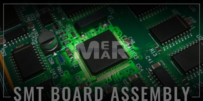
Surface-mount technology (SMT) electronic segment assembly intends to build electronic components utilizing automated machines that position components on the board’s surface (printed circuit boards, PCB).
SMT and the concerned SMDs, boost up the speed since they get directly placed on the board. Surface mount technology, or SMT, can be seen in all electronic copies we use. Since the elements used in SMT have a size reduction, the use of PCB becomes more beneficial and efficient.
Factors affecting the SMT Board Assembly Quality
The sureness with which SMTs (Surface mount) are mounted on PCBs (Printed Circuit Boards) throughout manufacturing is circumscribed by various elements, including Prototyping and fabrication, Surface mount devices’ design, positioning adaptation of the installation machinery engine, etc.
-
The BOM preparation
Since the content forms a significant part of SMT PCB Assembly, component effectiveness significantly impacts printed circuit board quality. It is crucial to be aware of the mentioned points:
- The elements labeling process should comply with the automatic machine design standards.
- The elements’ attribute complies with the automated design standards and meets the standardization plus measurement accuracy requirements.
- Soldering process requirements shall be satisfied by the soldering durability in the constituents and the PCB accessory. Before oxidation, the shortest ends and surfaces of the solder and the structure should be carried out. In specific, vacuum packaging should be made available for moisture control detectors and circuitry and located after when used in a storage container.
-
PCB pad manufacturability design
As per HP statistics, PCB design flaws account for 70% to 80% of production errors. Even if a bit of skew happens during the SMT process for a PCB with the correct pad design, it can be adjusted by the air pressure of the molten material, which is known as proactive placement. Even if the mounting position is exact, soldering imperfections such as element placement transfers and tombstone forms can develop if the PCB circuit structure is incorrect.
Therefore, designers must observe the following settlements in the SMT bearing design.
- Symmetry pad – To avoid sliding issues position and tombstone after solder reflow, for the 0805 or lower chip component, bearings at both ends must maintain the size of the symmetrical pad heat dissipation capabilities to maintain a balanced tense surface. This keeps the pad in a stealth mode apart from keeping it safe.
- Space between bearings – To ensure the exact size of overlap between the end of the component or tin and pad, when the space between the path is unevenly sized, solder defects can arise. The rest dimensions of the gasket must ensure meniscus solder joints after the end of the component.
- Width Pad should be able to fit its place, respecting all requirements of the pin itself.
- Don’t place Vias through the hole.
-
Printing using solder paste
The immediate aim of extrusion manufacturing methods is to solve the incompatible substrate printing amounts (filling amount and solder paste transfer amount). Due to inadequate solder paste printing, 60 percent of the PCB should be used for maintenance once it is properly configured.
-
Solder component quality
Storage and application go hand to hand in case of component quality associated with the PCB Solder. The paste is generally balanced between 0 and 10 ° C, or per the manufacturer’s needs. For its use, the optimum temperature of the SMT area must be 25 ° C ± 3 ° C, and moisture must be 50% ± 10%. The solder outcome cover must be corrected as per the specifications of the board. Also, the paste needs to be soldered within a certain period so that the board remains intact.
-
Template build
Stencils are mostly preferred for printing settlements. Solder printing is a necessary factor, and the stencils are responsible for delivering or affecting the appropriateness of the template. So far, there are three methods of making stencils: molten handling, application of high beam laser, and the process of electroplating.
- The thickness of the stencil plate- The design base must be smooth. The minor lead calculation must determine uniformity and steel plate thickness to ensure the number of solder outcomes and welding efficiency.
- Aperture Design- The concerned walls of the design have a shining polish and tend to be free of issues. Aspect ratio = aperture width / stencil thickness (for smooth QFP pitch, IC); Area Ratio = Openings / Basic Areas Area Wall Hole (0201, BGA, CSP).
- Soldering ball processing- Solder ball processing is implemented in the 0603 or above the chip component can effectively avoid the generation of soldering balls after REFLOW.
-
Scraper
Use a nickel-plated steel scraper, usually 60°. If there are hole parts, the 45° scraper is recommended to increase the TIN on the pieces through the hole.
-
Print Parameter
Printing parameters generally include certain things like the scraper pace, working thrust, speeding of the seed drop, freshening capacity, and repeating count. Excessive scraper pressure can cause insufficient tin and increase the wear between scraper and stencils, while external pressure causes incomplete solder paste printing.
-
Accuracy of the equipment
The precision of the printers and their consistency also influence the durability of the printing of circuit board pastes when produced with higher concentrations and timber. Pressure drove solder lead or patchy lead paste if the Board provides proper care or has suitable reinforcement. The PCB mounting should be level and perhaps even to achieve closeness between the design and the Circuit.
Conclusion
Many factors improve SMT soldering, including new statutory, PCB and solder filler efficiency, and PCB layout. Because these elements’ splicing wires’ imperfections are harder to pin down with technological problems, PCB design is the foundation of quality management for installing. As a result, effective inventory performance measurement and outstanding PCB patch design are two advantages of enhancing soldered reliability. We can predict that experts are preparing various surveys to make engineers understand the beneficiary facts of SMT. SMT is undoubtedly going to be the pace of technical aspects and building with a designated period.
Mer-Mar Electronics is an ISO certified company and ITAR (International Traffic in Arms Regulations) compliant manufacturer who deliver the best RoHS Compliant PCB Assembly services for over 4 decades. We have the capabilities to handle single-sided or double-sided, SMT or through-hole. Our consistent quality and quick turnaround time endear itself to our customers, who look at us as a one stop-shop for all their PCB requirements.
Get a quick PCB assembly quote!


