PCB fabrication process – A step by step complete guide!

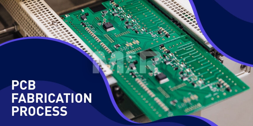
The use of PCBs (Printed Circuit Boards) has become quite ubiquitous as they bring electronic equipment-simple or complex, to life. Particularly in mission-critical functions where failure can be fatal, it is imperative that there are no errors in PCB fabrication. Here is a handy guide to the various steps of the process.
YOU MAY ALSO LIKE: Printed circuit board assembly process
PCB Manufacturing Process
1. Design
An important first step is the right design. At the PCB design stage itself, it is important to be in touch with the contract manufacturer. Among other things it is necessary to inform them of the design software being used so that there are no discrepancies. It is important that the design fulfills requirements for design for manufacturing (DFM) so that there are no issues faced at the fabrication stage.
2. From file to film
Post the DFM check, it is time for PCB printing. A special printer called a plotter is used for the process.
Each layer of the PCB and the solder mask gets its own clear & black film set. To ensure there is good alignment, registration holes are punched through the films.
3. Printing the Inner layers
In this step, the figure is printed on the film and onto a copper foil. The PCB comprises a laminate board where the core material is epoxy resin and glass fiber. Copper is pre-bonded on both sides. The whittling away of copper reveals the design of the films. Copper-sided laminate is cleaned. The clean panel next receives a photoresist, a layer of photo-sensitive film. Once the photoresist is exposed to ultraviolet light, it hardens. Once the board is prepared it is washed with an alkaline solution so that any photoresist that has not hardened is removed. The board is subsequently dried.
4. Removing the Unwanted Copper
At this stage, a powerful chemical is used to remove the excess copper. The desired copper, however, remains protected beneath the hardened layer of the photo resist. The hardened resist is now washed off with another solvent.
5. Layer Alignment and Optical Inspection
The inner layers are next aligned to the outer ones. The use of an optical punch ensures that registration holes are punched accurately. Automatic optical inspection of the panels is also carried out so that there are no errors.
6. Layer-up and Bond
In this step the layers are fused together. There are two steps involved
- Layer-up
- Bonding
The outer layer comprises of the prepreg. There is a copper foil that covers the top & bottom of the original substrate. To bond them together a heavy table with metal clamps is used. The prepeg layer is placed over the alignment basin. The substrate layer fits over the prepeg. Sheets of prepeg sit over the copper layer. Finally, aluminum foil & copper press plate are placed. Now it is ready for pressing.
The stack is heated up & then cooled in a controlled manner. The restraining pins are next removed, and the top pressure plate discarded
7. Drill
At this stage holes are drilled into the stack board. The use of an x-ray locator identifies the drill target spots after which the holes are bored. After the drilling is done the additional copper is removed with a profiling tool.
8. Plating and Copper Deposition
Chemical deposition is now used to fuse the different layers post drilling. The entire process of dipping, removal as well as procession is controlled using computers.
9. Outer Layer Imaging
At this stage photo resistance is applied to the outer layers of the panel. UV light is next passed on the photo resist. Unhardened resist is next removed.
10. Plating
The panel is electroplated with a thin copper layer. After the initial copper plating baths, they are followed by tin plating. The importance of tin is that it guards the panel which is meant to remain covered with copper during the etching stage.
11. Final Etching
During this stage, the tin protects the desired copper while the unwanted copper layer undergoes removal. Post this stage the conducting areas as well as the connections are properly established.
12. Solder Mask Application
The panels are now cleaned & covered with an epoxy solder mask. A blast of UV light ensures hardening. The board is finally passed through an oven to cure the solder mask.
13. Surface Finish
To add solderability to the PCB, they are plated with gold or silver. In some cases, hot air leveling is also carried out leading to the generation of surface finish. Explore many other types of PCB surface finishes and select the best for you.
14. Silkscreen
The completed board now receives ink-jet writing so that all vital information is captured.
You may also like: What is silkscreen in PCB?
15. Electrical Test
Electrical tests ensure that the PCB is functioning correctly & that it conforms to the original design. Flying Probe testing is particularly recommended to test electrical performance.
16. Profiling and V-Scoring
Finally, the boards are cut from the panel. For this either a router or a v-groove method is used. With either of these ways the completed board pops out of the panel.
The boards are now ready for shipping.
Mer-Mar Electronics takes care of every PCB fabrication step with predefined process. Get in touch with us via email on sales@mermarinc.com or give us a call at (760) 244-6149 to start the fabrication process of your requested PCBs.


