Categories

Archives

The PCB Components Assembly Process – A Complete Guide!
By Mer-Mar Electronics | Date posted: | Last updated: November 25, 2022
PCB Components Assembly

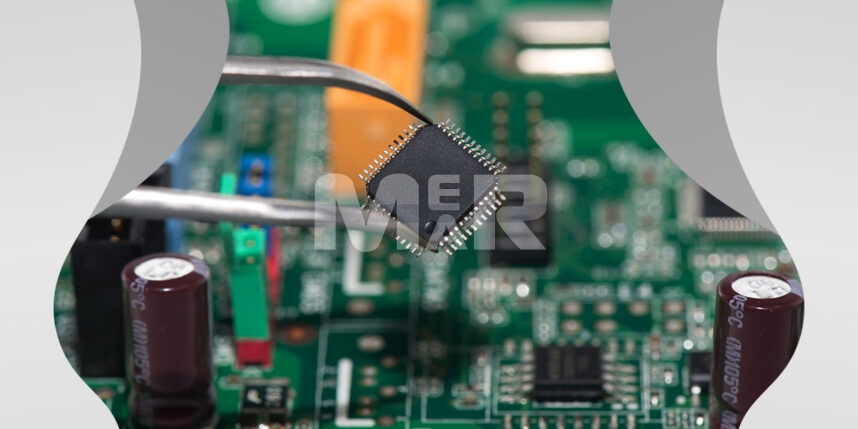
When it comes to the assembly process of PCB components, there are both automated as well as manual steps involved depending on the complexity of the board. Of course, the assembly process also has a lot to do with the fact whether the assembly is being done for through-hole components, surface mount components or whether they are mixed PCB components.

THROUGH-HOLE PCB COMPONENTS

Typically, these are components with long leads and are a generation behind surface mount components. These components involve that leads be inserted into holes and then soldering them. Typically such components are only mounted on the top end of the board.

PCB DESIGN

While designing PCBs with through-hole components, it is important to place the holes at distances that are specified by the component manufacturer. When dealing with multi layered printed circuit boards What is also important are plated through-holes. These holes also act as vias for connecting circuits on the outer layers.

For such boards since drilling of holes is a key requirement, the area that is available for routing of traces is limited. That typically means that you have to use a board with a large area that may not be conducive to the trend of miniaturization that is prevalent. Alternately, you can use a board with multiple layers.

COMPONENT MOUNTING

Whether you choose to use manual or automated component mounting, it is important that the component leads are pre-processed so that insertion becomes seamless.

SOLDERING

Largely, through hole components are soldered by a process of wave soldering. The machine throws up molten solder through a nozzle. As the components assembly passes over this wave, the components are soldered in place.

SURFACE MOUNT PCB COMPONENTS

For such components, the exercise of drilling need not be undertaken. In fact these are smaller components that can be packed together and they work particularly well in dense assemblies. Also surface mount components can be mounted on both sides of the board.

PCB DESIGN

Since space does not need to be allocated for the holes, a high component density is a given. High density is also achieved by using small vias or tented vias in pads when it comes to fine pitch components such as BGAs (Ball Grid Array packages).

SOLDER PASTE DEPOSITION

The use of a stencil to deposit solder pads at the right areas is important. Solder paste deposition may be manual or automated.

COMPONENT MOUNTING

Typically pick-and-place machines are used to mount small components. This ensures that each component is mounted in the right location with solder paste on the pads.

SOLDERING

Since solder paste is already present all that is required is to melt the solder so that the component is held in place. For this purpose, a reflow soldering machine comes in handy. It has infrared heaters that generate heat that melts the solder paste & fixes the components.

MIXED PCB COMPONENTS

Some applications make use of a mixed technology & hence use both surface mount as well as through-hole components.

PCB DESIGN

In such cases the surface mount components are typically placed on the underside of the board. This is advantageous as the wave soldering process ensures that they are soldered along with the through-hole components.

COMPONENT MOUNTING

For the surface mount components it is important to use a glue deposition process. Essentially a dispenser places glue between the pads. The pick-and-place machine next mounts the surface mount components. Pro tip – It is important for the board to go through a curing process so that the glues is sufficiently hardened & the component is held in place.

SOLDERING

It is now safe to turn over the board & insert the through-hole components. After this follows the wave soldering process.

To sum up

While PCB assembly of through-hole components seems simpler, the fact remains that there could be opportunities for failure. For example, if component leads are close there are chances of shorts. Also, a big disadvantage with through-hole components is that they do not lend themselves to high density assembly.

Surface mount components on the other hand can take care of many of these issues. The components can be packed densely. Also, with the reflow soldering process the quality of soldering is far higher.

Mer-Mar Electronics is one of the leading PCB manufacturing companies, providing all-in-one PCB assembly solutions. Our consistent quality & quick turnaround endear itself to our customers, who look on us as a one-stop shop for all PCB manufacturing requirements.

If you have any queries regarding our surface mount assembly or through-hole PCB assembly services, or need urgent assistance, then please do not hesitate to contact our team of skilled personnel. Send us an email with your queries at sales@mermarinc.com or call us at (760) 244-6149.

PCB Assembly Components
PCB Components Assembly
PCB Components Assembly Manufacturer
PCB Components Assembly Process
PCB Components Assembly Quotes
PCB Manufacturer
PCB Manufacturing
PCB Surface Mount Components
PCB Through Hole Components

What makes flex circuit assembly stand out from the competition?

By Mer-Mar Electronics | Date posted: | Last updated: October 17, 2022
Flex Circuit Assembly

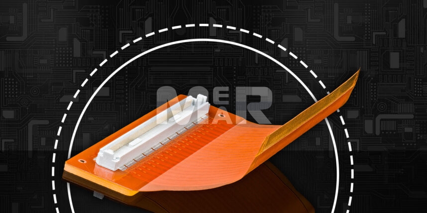
While for the most part we are used to circuit boards in their traditional formats, the growth of ergonomic product designs, as well as the evolution of wearable tech, necessitates a different kind of circuit board. You sure need boards to fit in miniature spaces as also for them to be resistant to vibration, mechanical wear and tear, and more.

All of these objectives can be achieved with a flexible circuit board. While earlier assembling flex circuits was prohibitively expensive both in terms of material and man-hours, flex assembly costs have been dropping, making it convenient to use them in everyday products.

Some of the many benefits that flex circuit board offer, include:

Ability to take different shapes

This of course is the most obvious advantage, as such boards can be bent and folded. It also allows components to be placed in optimal positions within the product. Essentially it lends itself to miniaturization of products, which is a growing trend.

Weight Reduction

Space, Weight and Packaging remain important issues when it comes to PCB design. With flexible circuits bulky wire and solder connections can be avoided. In turn, this leads to a significant reduction in weight and space and also in packaging size.

Reduced assembly costs

With bulky wire and cables being significantly reduced in flex circuits what is also reduced is the cost of wire as also the labor cost.

Helps with dynamic flexing

Flexible circuits can withstand flexing. Examples of this include disk drives, laptop hinges and more

Thermal management

Flexible circuits are frequently seen in high power, high frequency designs as polyimide materials can withstand high heat applications. Laos thin polyimide dissipates heat quickly.

Great for aesthetics

Flexible circuits work well in terms of product aesthetics, which is major draw for consumers. It lends itself to sleekness and rates high on consumer confidence.

Bio-compatibility

Polyimide materials are known for their bio-compatibility and hence find high application in medical as well as wearable applications.

High on Reliability

As opposed to a rigid board, a flex board can simplify the system design by reducing the number of interconnections required. This also takes away the possibility of human error and increases reliability.

Aspects to be kept in mind when it comes to flex circuit assembly, some of these include:

Customization

As opposed to rigid PCBs that can work with standardized dimensions and conveyor belt-style processes, flex circuits may need to be assessed individually. Some of the areas to pay importance to, include:

  • The pallet needs to fit its unique shape
  • The pallet needs to accommodate both the top and bottom circuit configuration
  • The flexible circuit assembly needs to lay flat on the pallet otherwise an air cushion beneath the circuit can cause mechanical resistance during solder paste screening as well as pick-and place. The air cushion also can cause components to bounce off the PCB assembly.
  • It requires special tooling and backup fixtures for unique designs
  • The pallet geometry needs to be customized so that the circuit remains flat.
  • Also with pick-and-place machines working at high speed and small margin of error, there can be issues if there is any difference between circuit dimensions and actual flex circuit geometry.

Heat Sensitivity

The other issue that needs due importance is that of heat sensitivity. Essentially, flex circuits are far thinner than rigid boards. On account of this, the heat that is applied in soldering cannot be dissipated. What is important is also that there should be precise soldering tools as well as extremely experienced technicians. It is only with the investment in the state-of-the-art tools as well as trained technicians that productivity can be improved.

Testing

Flex circuits require appropriate backing during the testing process. For example, in case of Flying Probe testing, there needs to be a special custom fixture to offer support to the PCBA. In case of in-circuit testing, a rigid backing is designed into the clamshell fixture.

With flex circuits increasingly solving the constraints, their use is likely to become even more ubiquitous.

Mer-Mar Electronics is one of the leading PCB assembly manufacturers, providing all in one PCB assembly and fabrication solutions. Whether you are looking for flexible PCBs, flexible PCBs fabrication or flexible circuit board assembly, we have you covered. Send us an email with your queries at sales@mermarinc.com or call us at (760) 244-6149 related to our flexible PCB manufacturing and assembly.

Flex Circuit Assembly
Flex PCB Manufacturer USA
Flex Rigid PCBs
Flexible Circuit Board assemblies
Flexible Circuit Boards
Flexible Circuit Boards Assembly
Flexible PCB Assembly
Flexible PCB Fabrication
Flexible PCBs
Flexible Printed Circuit Boards
PCB Manufacturer
PCB Manufacturing
PCB Manufacturing Services
Printed Circuit Board Manufacturing
Rigid PCBs
Rigid- Flex PCBs

A Complete Guide on PCB Soldering Process!

By Mer-Mar Electronics | Date posted: | Last updated: November 25, 2022
PCB Soldering Process

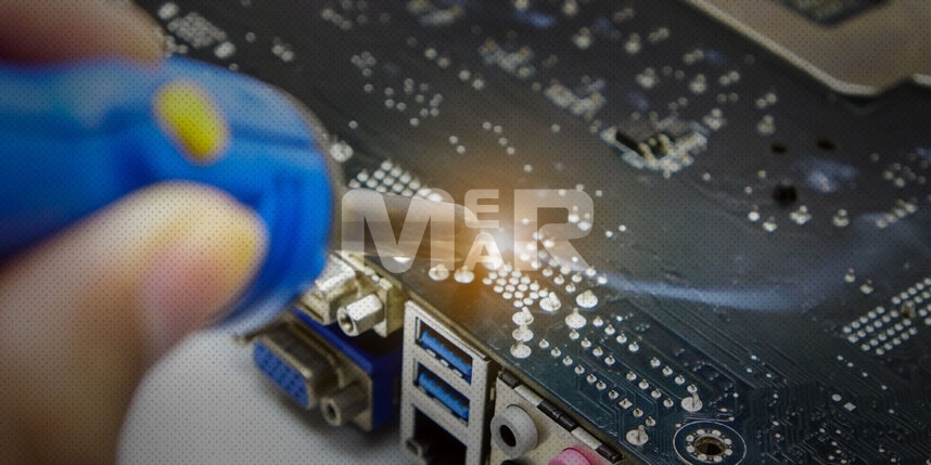
Soldering is an essential process that helps fasten components onto a PCB. The right soldering can make a huge impact on the quality as well as the performance of the custom printed circuit boards. In this article, we have explained what the PCB soldering process is, the types of soldering process; and how it can be done.

There are different types of soldering techniques as well as solders, the choice of which is critical to the success of your project. Here is a detailed overview:

Types of PCB Soldering Process

Reflow Soldering

This involves using a solder paste to temporarily attach components to their respective contact pads. Post this, the assembly is subject to controlled heat. The process of reflow soldering involves the following steps:

  • Application of the solder paste.
  • Preheating the board to bring it to the required temperature.
  • Thermal Soak so that areas that weren’t adequately heated come to the required temperature.
  • Reflow process to create the necessary solder joints and remove volatiles.
  • Cooling to prevent thermal shock and excessive intermetallic formation on the board.

Wave soldering

This is a large-scale soldering process wherein electronic components are soldered to create an electronic assembly. This process involves passing the PCB over a pan that contains molten solder. It is important to maintain the right temperature during wave soldering. There also needs to be adequate pre-heating as otherwise, the board is susceptible to stress.

The steps involved in wave soldering include:

  • Melting the solder
  • Cleaning of Components
  • Placement of components
  • Application of solder
  • Cleaning of the board

The ideal temperature during wave soldering ranges between 240-250°C.

Wave Soldering Vs. Reflow Soldering

The type of soldering you go with depends on a wide variety of factors including but not limited to:

  • Shape of the pads
  • The available time
  • Component orientations
  • Type of PCB, and more.

In some ways, wave soldering is more complex as its success depends upon creating the right environment. Board temperature and the time the board spends in the solder wave need to be monitored. However, wave soldering is also faster and more cost-effective as opposed to reflow soldering. Reflow soldering is however more suited to be used in small-scale manufacturing while wave soldering is suited for large scale production.

Explore the reflow soldering v/s wave soldering in detail.

Types of solder

Other than the soldering process, what is also critical is the choice of solder. Some of the solder types that are increasingly used include:

Lead alloy solder – It is a mixture of 60 percent tin and 40 percent lead.

Lead-free solder – Given the impact of lead on the environment, the use of lead-free solder has been growing. In fact, the EU has restricted the use of lead in consumer goods.

Silver alloy solder – These emerged as alternatives to lead solder and contain between 3-5 percent of silver.

Some Common Problems in PCB soldering process

Some common problems that one needs to watch out for in the soldering process, include:

Interfered joints

These joints result on account of movement during solder solidification. As a result, the joint appears crystalline and rough.

Cold joint/overheated joints

These result if the optimal temperature isn’t maintained or if the duration of heating isn’t long enough.

Excessive solder

If there is application of too much solder it results in bubble-like solder balls. In turn, they impact the functionality of the board.

Insufficient wetting

A badly wet joint results in poor connections and impairs the overall performance of the circuit.

Solder hunger

This refers to a situation where insufficient solder is used. In turn, it leads to poor electrical contact between the parts of the circuit

Untrimmed leads

If the leads aren’t trimmed to the required lengths, there can be the risk of short circuit as the leads can come in contact with the rest of the charges.

Points to be kept in mind during PCB soldering process

#1. Heat dissipation during assembly

It is important to effectively monitor heat dissipation during assembly and to ensure that the circuit’s components remain below the required temperature limits.

#2. Keep the soldering iron tip clean

If the soldering iron tip isn’t kept clean, you can run into a number of issues including low heat transfer leading to soldering issues.

#3. The sequence of welding parts

It is important for designers to understand the right sequence of affixing the various components.

#4. Removal of residue

Once the soldering process is complete, you are left with the flux. This needs to be thoroughly cleaned as otherwise it can lead to low voltage insulation short.

#5. Soldering SMT resistors and capacitors

Soldering resistors and capacitors is a challenging task. Experienced PCB designers can make a great deal of difference in this process.

#6. Continuity and Sensor Output

It is imperative to undertake testing for continuity and sensor output to ensure that there are no malfunctions.

To Sum Up

The right soldering is a matter of precision and having enough experience and access to soldering best practices. It is important, therefore, to go with the right partner who can make a difference to the project.

Mer-Mar Electronics is one of the leading PCB manufacturing companies, providing all in one PCB assembly and fabrication solutions. Our consistent quality & quick turnaround endear itself to our customers, who look on us as a one-stop shop for all their PCB manufacturing requirements. In case you have any questions or require more information about our PCB manufacturing services, contact us via email at sales@mermarinc.com or call us on (760) 244-6149.

PCB assembly soldering
PCB Manufacturing
PCB Soldering
PCB Soldering Process
PCB Soldering Technology
PCB Soldering Tips
PCB Wave Soldering
PCBs
Printed Circuit Boards
Reflow Soldering
Soldering PCB Board
Wave Soldering Vs Reflow

The Essential Guide to Wire Harness Manufacturing Process

By Mer-Mar Electronics | Date posted: | Last updated: February 22, 2022
Wire Harness Manufacturing Process

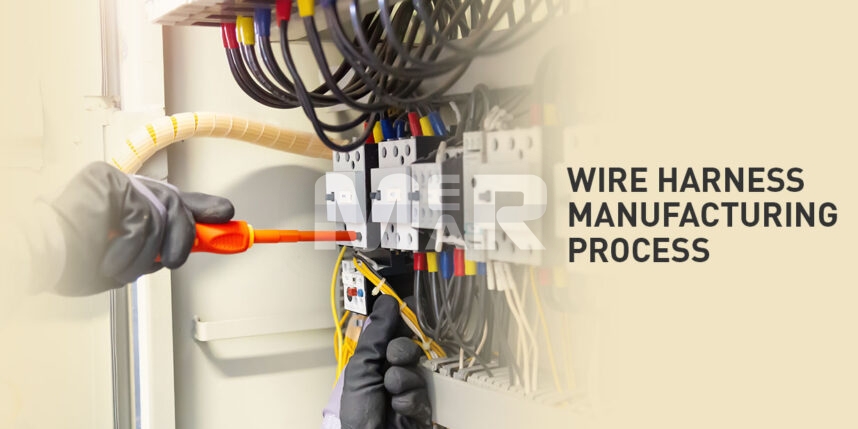
Wire Harness Manufacturing process is an extremely specialized process that involves several measured steps. Before we get into them, let us look at the difference between a cable assembly and a wire harness.

Simply put a cable assembly is an external connection to devices and needs to take into account factors such as:

  • Thickness
  • Flexibility
  • Type of insulation

A wire harness, on the other hand, offers connectivity between systems in an electromechanical assembly. Wire harnesses are built on panels that has pegs. The harness, therefore, is laid out to bespoke dimensions. It is important to remember that the more detailed and precise the specifications, there will be fewer issues on the assembly floor. Some of the information that the contract manufacturer will require in order to build the wire harness, includes:

  • Connector images with pin locations
  • Wire lists
  • Detailed BOM with part numbers
  • Assembly drawing
  • Test specifications

Best Practices in Wire Harness Design

The benefits of good wire harness design includes the fact that it improves the service life of wires, optimizing the space required for wires, organizing all wires in one place for easy access. It is imperative therefore that best practices be followed when it comes to wire harness design.

Some of the best practices in wire harness design include:

  • Identifying problems that could be posed by the physical environment such as moisture, temperature, electrical interference and more.
  • Choosing the correct routing option.
  • Ensuring that exact measurements are adhered to when it comes to cutting wires and calculating the bend radius.
  • The harness must fit correctly in the space it is intended for. It is important, therefore, to take the size of the outer protective casing into account.
  • The type of terminals and how they fit into the wire radius is also an important design decision.

Important Steps in the Manufacturing Process to Build Your Wire Harness

The broad steps followed by contract manufacturers to build a wire harness include:

  • Robust design review – Basis your design, the contract manufacturer will examine the entire documentation and Bill of Materials to see that everything is in place.
  • Preparing the material – Post finalization of the Bill of Materials, the components and materials required for production and test of the harness are purchased.
  • Assembly documentation – The Contract manufacturer will also create a detailed Assembly Documentation including:
    • Assembly steps
    • Images
    • Test procedures.
  • Prototype – Typically before producing the wire harness, the contract manufacturer creates a prototype. This helps to perfect the assembly and to ensure that the quality expectations are met.
  • Production of Wire Harness – The building of the wire harness involves cutting the wire to length and laying it on the assembly panel. The next steps involve adding connectors, tying bundles of wires and attaching labels.
  • Testing – A detailed testing protocol is finally undertaken. The harness is checked for a number of issues including:
    • Construction
    • Labeling
    • Checked for usage on-site

Dos and Don’ts to be followed in building the Wire Harness:

Below are some of the tips to be followed when it comes to building the wire harness assembly:

  • The termination recommendations for attaching the wires need to be followed. The recommendations could be in the form of stripped and bare or stripped and tinned.
  • Similarly, the recommendations for torque values on fasteners need to be followed.
  • Generic specifications for wires such as 300V or 600V need to be adhered to. It is best not to give the contract manufacturer a specific UL code. That way the contract manufacturer can use wires that fit the requirement, are available and that are cost-effective.

As a thumb rule it is imperative that you work with the contract manufacturer from the early stages of development so that the electronic contract manufacturer can help with the selection of best performing parts. Additionally, it is advisable to go with a contract manufacturer that has experienced engineers with the necessary expertise who are equipped with industry best practices so that you do not land up making any costly mistakes in the wire harness manufacturing process.

Mer-Mar Electronics has been in the business for over 40 years and has a skilled & experienced engineering team who works on different design systems. Our manufacturing experts build your PCBs, cable assemblies, wire harnesses, and more. In case if you have any questions or require more information about cable and wire assemblies services, get in touch with us via sales@mermarinc.com or call us on (760) 244-6149.

Cable and Wire Harness Assembly
Cable Harness Assembly
PCB Assembly
PCB Manufacturer in USA
PCB Manufacturing
PCB Manufacturing Process
PCBa
PCBs
Printed Circuit Board Assembly
USA PCB Assembly
Wire Harness Assembly
Wire Harness Design
Wire Harness Manufacturing Process
Back to top